# FFXIV model Vertex limit
This is a document explaining what the rough "vertex" limit is for 14, how it is calculated, and how you can figure out how to lower it if you get a warning.
# Why is the vert count not the real vertex limit? (the basics)
This guide is currently being updated for Dawntrail, however It is being posted as-is for archival purposes until updated. The general concepts are still correct.
This document was originally created by Kora, and was updated by me to account for penumbra's existance, and Dawntrail's graphical update. A lot of the information in this document was adapted from thier document and was edited and posted with Kora's permission.
#### What's a vert limit and why do I care?
A common question when getting into modding for 14 is what the limits are for your 3d model to be imported into the game. The most often asked limitation is the hard limit/maximum polygon/vertex count a model can have; and it can be pretty confusing because there are lots of answers floating around. Some say you shouldn’t have more than 40k vertices, some say you can’t have more than 20k polys, and others still say the limit is 65k indices (what does that mean?) per mesh group. **So which is it?**
### The FF14 .MDL format
There is no exact vertex or polygon count limit or else there wouldn’t be so many answers floating about. The cause of this is due to the way the 3D model’s data is stored in the game’s files. Final Fantasy XIV uses Square Enix’s MDL file format to store 3D model data. This format can store data of up to 65,535 (the maximum value of an unsigned 16-bit integer) vertices per mesh group. This is where the 65k vertex index limit answer comes from. **Ok so that’s easy, the limit per mesh group of my 3D model is then just 65k vertices! Yes, but also no.**
Vertices aren’t the end of the story
The model that you have open in your 3d program can’t just be imported into the game as is and requires some adjustments during import. The main difference becomes apparent (and can be confusing) when you export and look at a model that you previously imported into the game. Vertices that were previously welded are now unwelded and all the vertices along UV seams are now split. But why is that?
In 3d software, a single vertex can have two faces with different data attached to it (also known as “per face data”). Most game engines including ff14 cannot handle this type of data. All modern 3d software will “split” your edges/verts in order to accommodate this. This trait occurs across the FBX, OBJ, and GLTF/GLB formats
This means that any verts along a hard edge, uv edge/seam, or any verts along a material border will be split into 2 or more verts on export.
Every single vertex must contain a complete (position, mesh/vert normal, vertex color, Uv coordinate, and weights) and unique set of data to be read properly in 14.
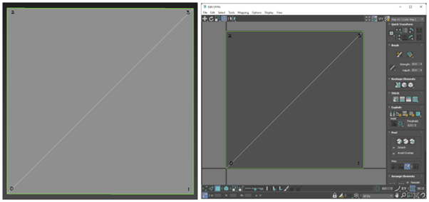
As an example, look at this square plane. This plane will import into the game without any changes as each vertex only contains one complete set of position, normals, vertex colour, UV coordinate and weight data..
[](https://xivmodding.com/uploads/images/gallery/2024-12/SJEsYI3D2eyDZ1U0-image.png)
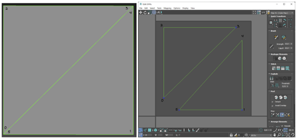
On the other hand, if there were a UV seam on the diagonal edge of this plane the situation would be different. **The vertices in the bottom left and top right corner of the plane now have two sets of UV coordinates so this plane will be split into a total of 6 vertices on import even though there might still only be 4 vertices in** **your 3d software. **
[](https://xivmodding.com/uploads/images/gallery/2024-12/5uBChs0trK1IwoUj-image.png)
It is important to remember that the vert and polycount that your 3d software lists is not going to be the exact same as the final count after export. You should always keep that in mind, and try to optimize your edge flow and your UV edges/islands to limit the amount of splitting that export will cause, or duplicate the verts manually (in blender, this is referred to as ripping the edge)
As a note, when showing counts in maya, while the vertex count will not match the amount after export, the UVs count will properly “split” verts on a UV edge or seam. While this number won’t be exact to the amount of verts post import, if you decide to use maya, use the UV count instead of vertex count to determine how close you are to the hard cap. Unfortunately you cannot do this in 3ds max or blender, as they do not show UV count, only vertex count, poly count, tri count, and edge count, so you will need to be more mindful of your UVs.

this is a gif of the same plane, but in maya. Watch how the UV count changes as the edge is split to create a new UV seam.
### In conclusion...
There is no easily defined vertex/poly limit for a given model. It depends on the complexity of your model and how easily it can be converted to fit the format that the game uses. The better your mesh and the UVs are optimized, the closer the in program vert count will be. **The vertex count of the imported 3D model will always be equal or more than the vertex count you see listed in your 3D modelling program. A good rule of thumb is to limit yourself to about ~40-50k vertices or ~15k tris per mesh group. This usually leaves plenty of headroom for any required adjustments to the model while not exceeding the hard vertex *index* limit of 65,535.**
If you find that your mesh is too close to the limit, or you have multiple mesh groups at the limit/you have to split your mesh into a bunch of mesh groups to get under the limit, it is recommended that you retopologise your mesh instead of splitting into groups.
# Extra notes (and dawntrail notes pre-reformatting)
##### This page contains extra notes and things you should be aware of, that don't cleanly fit into the main page.
glTF stores vertex data in the format expected by GPUs for faster loading / viewing in engines. This requires splitting shared per-face normals and UVs, with per-face normals generally increasing vertex counts more. If your model happens to use *only* per-face normals, you can just uncheck *Geometry → Normals* at export. If normals aren’t exported they won’t split vertices, and glTF viewers will infer flat normals.
Most meshes should not need to hit the new vert limit if you are properly retopologizing and optimizing your meshes. however it is common for fur and hair to get close to the limit, as many modded hairs and furs use Hair Cards, which are inherently vert-heavy. on top of this, hair generally needs shape keys for hat compatability. If you find that you are working on a hair and getting errors about vert/olycounts being too high, make sure you have split your mesh into multiple groups based on what does and does not need to change with the shapekey, to ensure that the only verts being counted multiple times for the shapekey are the ones actually deforming for the hat compatability. This would essentially look like having group 0 being your scalp/hair that goes under the hat, and group 1 being the hair that does NOT go under the hat.
Be mindful with vert and polycounts, as high counts can and will either crash mare users, or simply not be sent over mare at all because they exceed the filesize/polycount limit. if you want the best chance of your mod transmitting over mare, try to not get close to the maximum indice count. Even pre-dawntrail mods with high vert counts (which were lower pre-DT) were crashing mare users due to unoptimized polycounts. If you aren't sure hot to retopologize, there are lots of online tutorials and blender plugins to do a good enough job. just remember to do this before texturing and weight painting for the least amount of headache.
#### Information for further reading on this topic
[https://blenderartists.org/t/export-to-glb-weird-vertices-count/1376439/2](https://blenderartists.org/t/export-to-glb-weird-vertices-count/1376439/2)
In 3ds Max, they all have exactly **2964** vertices and **5924** faces. But when I export to glb they all vary between **3316** and **3341** vertices, so morphing is not working
I have tried both Babylons 3ds Max Exporter and the native glb exporter in 3ds Max, with the same result.
The only solution I have found so far is setting “Quick Export” in the Babylon Exporter, which then exports every model with exactly **17772** vertices, but that unfortunately quadruples the file size. (390mb in total, vs 90mb without “Quick Export”)
I have found another fix, which is splitting the edge (created with Shell modifier) into a separate mesh. This creates two meshes with consistently **2964** and **300** vertices across all models
I can possibly answer the why. If you have a UV map on a mesh, every UV seam will split vertices. And by glTF specification, all UV seams are unwelded when saved. In practice this doesn’t matter much as the baked normal on the vertex won’t show a lighting artifact, and you will likely only see the split seam if you are doing vertex displacement. This is an optimization since the format is a runtime format and not meant as a format to share files for editing. This is likely why you are seeing a difference in vertex count on export.
[https://forum.babylonjs.com/t/vertex-count-when-exporting-from-3ds-max/38240/4](https://forum.babylonjs.com/t/vertex-count-when-exporting-from-3ds-max/38240/4)
Is it standard practice to separate your model at the seams for game asset creation? (keeping it as one object). Ive extracted quite a bit of game assets and they're all split up into multiple pieces at the UV seams. Just wondering if this is standard in the industry and whats the reasoning behind it?
It's standard for game coders to not bother programming anything they don't need. One thing they don't need is face-corner data-- split vertex data. All they need to render the game is vertex data.
Your video card has no conception of face-corner data. It doesn't know this face has this UV and that face has that UV. It only knows that a vertex has a certain UV, which is interpolated across all of the vertex's faces. Yes, that means that even if you don't rip your seams, those vertices are still being calculated twice (or more) by your video card. If game developers want to handle face-corner data, they need to do that internally.
But they don't need to handle it. Face-corner data is a convenience for artists, but it's not necessary for games. If you need a UV seam or sharp edges or discontinuous vertex color, you can just double your vertices at that discontinuity. And it's trivial to build that into an export algorithm.
· Select a seam, then press `Shift G` to select similar and choose Seam. This will select all seams in the model
[](https://i.stack.imgur.com/lRv5G.gif)
· Press `Ctrl V` and choose Rip Vertices. This will separate the edges, and create overlapping edges each belonging to the different side of the seam
[](https://i.stack.imgur.com/xs8yd.gif)
· Press `P` to separate mesh, and choose By Loose Parts. Now you have different objects separated by seams of the original mesh
[](https://i.stack.imgur.com/LupBa.gif)
· Not every seam will result in a loose part. We can undo the ripping of these vertices by merging the vertices by distance
[](https://i.stack.imgur.com/w1i4t.gif)
[https://blender.stackexchange.com/questions/263085/splitting-objects-at-uv-seams](https://blender.stackexchange.com/questions/263085/splitting-objects-at-uv-seams)
Maya shows 486 verts, Imported mesh has 3.1k?
I have a mesh that has 486 verts in maya, but jumps 20 3.1k verts in Unity. It had a bunch of UV's originally, and I deleted those and the history to be safe, but it didn't help.
I'm pretty new with Maya, so please forgive me if this is a dumb question.
> Well, I'm no expert on how Unity handles geometry on import, but there are a few things from general game development that may be causing your issues.
>
> Most rendering engines need to duplicate verts to achieve certain rendering looks, so here are some of the most common things to look at.
>
> 1) Hard edges. If you have lots of hard edges on your model, most engines will duplicate the verts of the hard edge to achieve the look.
>
> 2) UV borders. Check to make sure you don't have any un-necessary UV border edges. You can tell Maya to display UV borders and they will appear on you model as thicker edges. If you turn on border edges and your model is covered with thick lines, this may be your problem.
>
> 3) Material boundries. Multiple materials/textures applied to the same object can cause duplicate verts, as well.
>
> Another posability is tri-stripping. I don't know if Unity tri-strips the models, but that can cause TONS of duplicate vert if you don't understand how tri-stripping works.
>
> Hope some of those tips point you in the right direction.
>
> Any more Maya questions, feel free to ping me.
I have an issue much like this, and other's I've seen posted.
I always get more verts than I have inside Max or Maya. I've done different tests to see where things are going wrong but it seems to differ with each attempt.
Exporting a cube out of Max actually multiplies the verts times three. But exporting my soft edged obj made in Maya with an original vert count of 761, now has 1.7k verts in Unity.
Are you reading the vertex count from the stats window in the game screen?
from what i gather unity adds up verts for every material you have applied to your object, also the number of lights affects this as well.
I think it is saying that's the number of verts processed, not how many the object has.
Maya might do the same as Max: Count the physical verts and tris not regarding split uvs and hard edges (smoothing groups)
Unity counts differntly, all "hard edges" and split Uvs make extra verts.
So the tris number usually not match
Shaders effect the physical number of times a tri is drawn to the screen. If you have a shader that requires two passes, it is the same as doubling the triangle count for the triangles that have the shader applied. If you have 24 faces of a mesh that have a two pass shader applied, it is the same as having 48 faces.
This is all based on the way the previous engines I used worked, Renderware and Unreal, and numerous in house engines.
I suppose it would depend on where in Unity you were looking at teh numbers, and how Unity reports the numbers.
All programs should be able to produce either eight or twenty-four vertex cubes. The reason for this is normals and smoothing:
Picture the corner of a cube. It is shared by three sides, each of which faces in a different direction. Because a vertex can only have one normal, each corner has to be triplicated in order to get a version with each normal.
A cube with twenty-four vertices will look like you'd expect a cube to look, with hard edges. An eight vertex cube will always have a gradient on each side, which will make it look like it's from an old, Gouraud-shaded 3D game. That is, it won't look like a real cube.
Turn on "view vertex normals" in your 3d app to see how many times the vertices are being split. Not sure how to do this in C4D but I bet you can.
[https://forum.unity.com/threads/maya-shows-486-verts-imported-mesh-has-3-1k.20776/](https://forum.unity.com/threads/maya-shows-486-verts-imported-mesh-has-3-1k.20776/)
This is from the Unity docs (*this is not Blender-related!!!*):
“The Unity Editor shows too many vertices or triangles (compared to what my 3D app says)
This is correct. What you are looking at is the number of vertices/triangles actually being sent to the GPU for rendering. In addition to the case where the material requires them to be sent twice, other things like hard-normals and non-contiguous UVs increase vertex/triangle counts significantly compared to what a modeling app tells you. Triangles need to be contiguous in both 3D and UV space to form a strip, so when you have UV seams, degenerate triangles have to be made to form strips - this bumps up the count.”
[https://blenderartists.org/t/exporting-obj-and-fbx-physically-break-edges-no-love-for-the-game-making-community/574448/20](https://blenderartists.org/t/exporting-obj-and-fbx-physically-break-edges-no-love-for-the-game-making-community/574448/20)
> 1. for XIV character shaders, a vertex is that:
>
> 2. struct VS\_Input
>
> 3. {
>
> 4. /\* v0 \*/ float3 position : POSITION0;
>
> 5. /\* v1 \*/ float4 color : COLOR0;
>
> 6. /\* v2 \*/ float3 normal : NORMAL0;
>
> 7. /\* v3 \*/ float4 texCoord : TEXCOORD0;
>
> 8. /\* v4 \*/ float3 tangent : TANGENT0;
>
> 9. /\* v5 \*/ float4 binormal : BINORMAL0;
>
> 10. /\* v6 \*/ float4 blendWeight : BLENDWEIGHT0;
>
> 11. /\* v7 \*/ int4 blendIndices : BLENDINDICES0;
>
> };
(Sorry I know the format readability is bad, I don't know how to fix it.)
### Dawntrail Notes (to be added to main page later)
The graphics update changed some things, and how we can think of the data. I will rewrite the portions of the main page to have this data later, but it is being put here for reference purposes.
> therefore indice/data count is roughly 8,388,600. if this number is bytes, and each "vert" counted the max amount of times is 56 bytes that would mean the max is roughly 149,796 verts.
While I cannot recall if this is per mesh or per group, it should be relatively easy to check.
Technically speaking you could go up to around 200k, however this is with the idea that most of your verts have much less data than the maximum a vert can hold. meaning:
- Only one UV set (no UV2, or 3)
- Not on an edge
- Not on a sharp point
- No vert color
- Less than 4 bone influences
- Not on a UV seam
- Not part of a shapekey
- etc
your Worst-case scenerio is ~150k "verts" (indices) but you can potentially go higher if you are smart with your data.
> re: the data thing. basically a vert can get "counted" multiple times at the end. so like here, my number of verts is 9805, but it's saying the individual UV points is 10660. that's bc any vert that was on a UV edge got "counted" multiple times
>
> [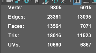](https://xivmodding.com/uploads/images/gallery/2024-12/5TWwxkqzVgl6bScG-image.png)
>
> idk why maya is apparently the only program to show UV point count alongside everything else, but yeah
> that's why technically speaking the "hard" vert limit isn't a thing, bc it'll vary based on your model. hence the "soft" limit i calculated by assuming every vert gets "counted" the maximum number of times
> sel found the byte (aka file size) limit, but that doesn't cleanly translate into a vert count or polycount limit bc 3d modeling is a curse
> The net final end count (particularly if using shape data) is 65,535
>
> DT's (limits) are more or less 2^16
So the end limits are roughly 150k (if all verts have the max amount of data) without shapekeys, and 65.5k with shapekeys.